This is a cache of https://www.owenscorning.com/en-ca/roofing/install-instructions/oakridge. It is a snapshot of the page as it appeared on 2026-04-09T06:55:33.931+0000.
Oakridge® and TruDefinition Duration® Oakridge Shingles Installation Instructions | Owens Corning Roofing Skip to main content

CAUTION: DO NOT MIX MATERIAL BEARING DIFFERENT LOT NUMBERS, REFER TO THE LOT NUMBERS LOCATED ON THE SIDE OF THE BUNDLE

Application Instructions

Before installing this product, check local building codes for roofing requirements.

These shingles are designed for new or reroofing work over any properly built and supported wood roof deck having adequate nail holding capacity and a smooth surface. Must comply with local building codes.

Precautionary Note:

The manufacturer will not be responsible for problems resulting from any deviation from the application instructions and the following precautions:

  • Roof Top Loading: Lay shingle bundles flat. Do not bend over the ridge.
  • Cold Weather Installation:
  • All field shingles must be installed with an approximate 1/16 inch – ⅛ inch gap on all end/butt joints.
  • This ensures that any expansion of the shingles which may occur in warmer weather will not cause the shingles to buckle against one another.
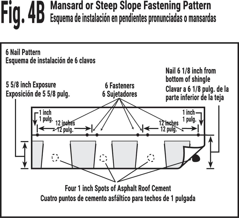
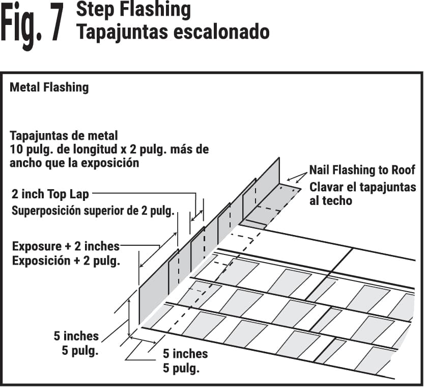
  • All shingles installed on the perimeter of the roof must be hand- sealed with four 1 inch dabs of ASTM D4586-compliant asphalt cement. (See Fig. 4B)
  • This protects against wind uplift which may occur when the temperature is too low for the adhesive strip of the shingles to activate.
  • Roof Deck: Minimum 6 inch roof deck boards, minimum 3/8 inch plywood, minimum 7/16 inch OSB sheathing spaced minimum 1/8 inch and maximum 1/4 inch. Regardless of deck type used, the roofing installer must:
  • Install the deck material in compliance with the APA — The Engineered Wood Association and local code requirements.
  • Prevent the wood deck from getting wet before, during and after installation.
  • Ventilation: Must comply with local building codes. 
  • Handling: Use extra care in handling shingles when the temperature is below 40°F. 
  • Storage: Store in a covered, ventilated area at a maximum temperature of 110°F. Bundles should be stacked flat. Do not store near steam pipes, radiators, etc. 
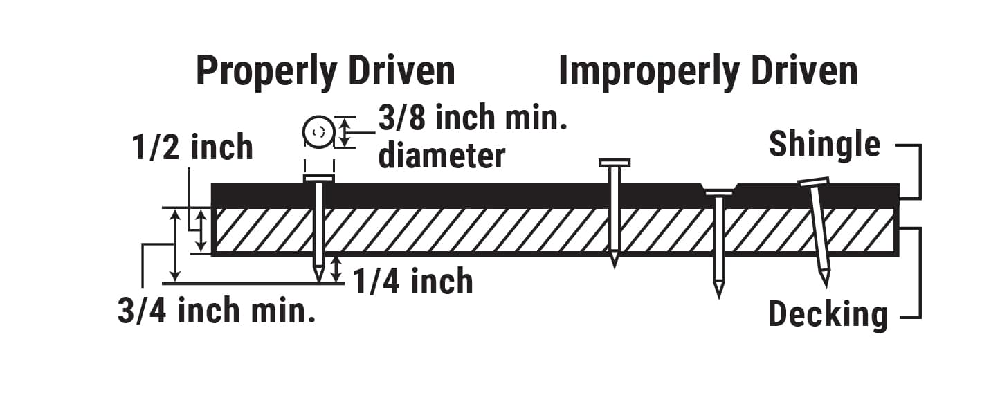
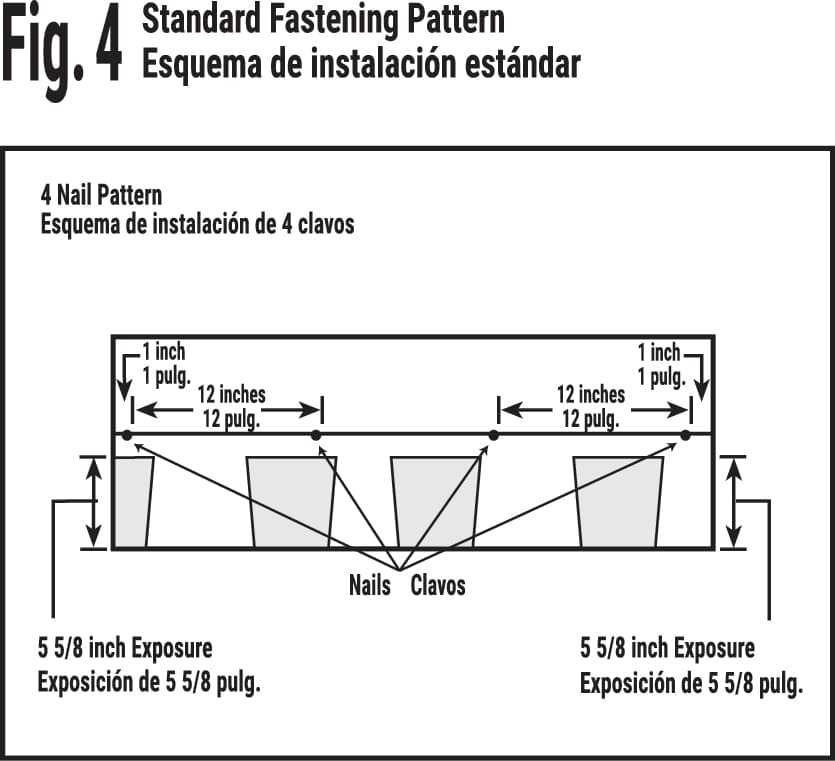
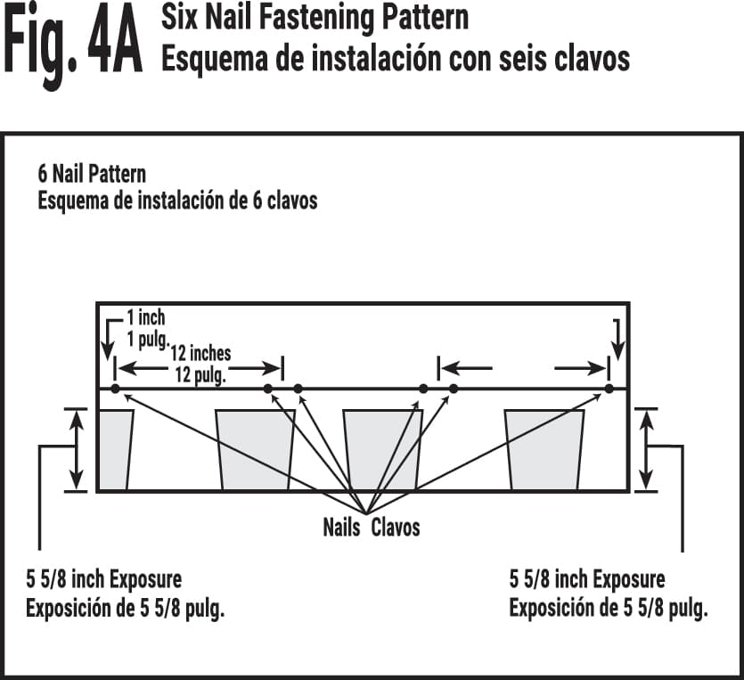
  • Fastener Requirement: Use galvanized steel, stainless steel or aluminum nails minimum 12 gauge shank and 3/8 inch diameter head. Owens Corning Roofing recommends that fasteners comply with ASTM F1667. Must comply with local building codes.

    All fasteners must penetrate at least 3/4 inch into the wood deck or completely through the deck by a minimum of 1/4 inch. 

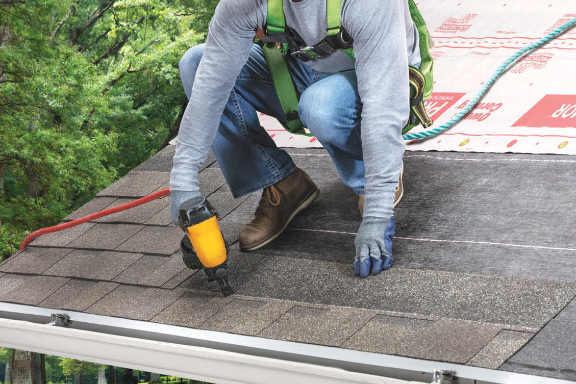
Notice: Owens Corning Roofing requires the use of nails as the method of attaching shingles to wood decking.

Properly Driven Nail Diagram

Step 1:

Self-Adhered Ice & Water Barrier

Use an Owens Corning® Self-Adhered Ice & Water Barrier on the eaves in all regions of the country where roofs have had a history of water backup due to ice dams. Apply starting at the eave’s edge and extend upslope a minimum of 24 inches from the interior wall line, measured horizontally. Follow underlayment manufacturer’s installation instructions and local building codes. Most applications will require 2 courses of self-adhered underlayment. See Fig. 1.

Fig. 1

Step 2:

Synthetic Underlayment

Standard Slopes 4:12 and Greater: Use an Owens Corning®, RhinoRoof®, or Titanium® Brand Synthetic Underlayment or equivalent underlayment meeting ASTM D8257. Follow underlayment manufacturer’s application instructions and local building codes. See Fig. 2.

Fig. 2

Step 3:

Synthetic Underlayment

Low Slope — 2:12 to Less than 4:12: 

Option 1: Install 2 layers of Owens Corning®, RhinoRoof®, or Titanium® Synthetic Underlayment or equivalent underlayment meeting ASTM D8257. Underlayment must be installed per the manufacturer’s application instructions and local building codes. Each underlayment course must be overlapped a minimum of ½ the width of the underlayment course below, ½ plus 2 inches, or in accordance with local codes. See Fig. 3.

Option 2: Install Owens Corning® Self-Adhered Ice & Water Barrier or equivalent with a standard overlap of 3 inches and metal drip edge. See Fig. 3A.

Fig. 3 and 3A

Step 4:

Shingle Fastening Pattern

Standard Fastening Pattern

Fasteners must be placed in the fastening area. See Fig. 4.

Fig. 4

Six Nail Fastening Pattern

Use 6 fasteners. See Fig. 4A

Fig. 4A

Mansard or Steep Slope Fastening Pattern

Place fasteners 61/8 inches from bottom edge to penetrate both layers of the shingle. Fasteners should be located 61/8 inches above the butt edge of the shingle, regardless of whether they are in the granules or the fastening area. See Fig. 4B.

REQUIRED: For slopes exceeding 60 degrees or 21 inches per foot, install 6 fasteners and 4 spots of asphalt roof cement per shingle. Immediately install a 1 inch diameter spot of asphalt roof cement under each shingle tab, centered 2 inches up from the bottom edge of the shingle tab. Center asphalt roof cement 2 inches up from bottom edge of shingle tab. See Fig. 4B.

Where required, asphalt Roof Cement shall meet ASTM D4586 Type I or II. 

Note: Please be aware that excessive amounts of asphalt roof cement may blister the shingle.

Fig. 4B

Starter Course

Use an Owens Corning® Starter product. Trim 61/2 inches off the rake or hip end of the starter course shingle and overhang the drip edge along the rake and eave’s edge 1/4 to 3/4 inch, and continue across the roof. Use 5 fasteners for each shingle, placed 2 to 3 inches from leading edge. See Fig. 5. Shingles must extend a minimum of ¼ inch and no more than 1 inch from rake and eave’s edge. They may be left flush with the drip edge if it is “D, F, or T”-style. 

Fig. 5

Step 5:

Shingle Application

Oakridge® shingles are applied with a 6½ inch offset, with 5⅝ inch exposure, over prepared roof deck, starting at the bottom of the roof and working across and up. This will blend shingles from one bundle into the next and minimize any normal shade variation. Application with offsets of 4 inches to 8 inches are also acceptable. Shingles and fasteners must be installed to ensure that end joints are no closer than 2 inches from the fastener in the shingle below and the offsets are not less than 4 inches in all succeeding courses.

First Course

Apply first course starting with a full shingle even with the cut rake or hip edge of the starter course. See Fig. 5A. Fasten securely according to fastening instructions. See Fig. 4.

Fig. 5A

Second Course

Remove 6½ inches of the first shingle and apply the remaining piece over and above the first course shingle and flush with edge of the first course with 5⅝ inch exposure. See Fig. 5B. Fasten securely according to fastening instructions. See Fig. 4.

Fig. 5B

Third Course

Remove 13 inches of the first shingle and apply the remaining piece over and above the second course shingle flush with edge of the second course with 5⅝ inch exposure. See Fig. 5C. Fasten securely according to fastening instructions. See Fig. 4.

Fig. 5C

Fourth Course

Remove 19½ inches of the first shingle and apply the remaining piece over and above the third course shingle and flush with edge of the third course with 5⅝ inch exposure. See Fig. 5D. Fasten securely according to fastening instructions. See Fig. 4.

Fig. 5D

Fifth Course

Remove 26 inches of the first shingle and apply the remaining piece over and above the fourth course shingle and flush with edge of the fourth course with 5⅝ inch exposure. See Fig. 5E. Fasten securely according to fastening instructions. See Fig. 4.

Fig. 5E

Sixth Course

Remove 32½ inches of the first shingle and apply the remaining piece over and above the fifth course shingle and flush with edge of the fifth course with 5⅝ inch exposure. See Fig. 5F. Fasten securely according to fastening instructions. See Fig. 4.

Fig. 5F

Succeeding Courses

For succeeding courses, repeat instructions for the first through sixth course above. See Fig. 5G.

Fig. 5G

Step 6:

Valley Construction

Closed-Cut Valley: A closed-cut valley can be used as an alternative to woven and open valley and is applied as follows: 

  • Lay a 36 inch wide valley liner of self-adhered underlayment or equivalent. A 36 inch wide minimum 50 lb. smooth surface roll roofing complying with ASTM D3909 or ASTM D6380 can also be used as a valley liner.
  • Lay all shingles on one side of valley and across center-line of valley a minimum of 12 inches; the first course on both sides should be woven.
  • Fasten a minimum of 6 inches away from center-line on each side of valley.
  • Strike a chalk line 2 inches from the center-line of the unshingled side.
  • Apply shingles on the unshingled side up to the chalk line and trim the excess off, taking care not to cut the underlying shingles.
  • Clip upper corner of these shingles and install a 3 to 4 inch wide, continuous bead of roofing cement.
  • Press shingles firmly into cement. Both woven and metal valleys are acceptable alternatives. See Fig. 6.

For California-Cut Valley, see technical bulletin at www.owenscorning.com.

Fig. 6

Step 7:

Step Flashing

Step flashing should be a corrosion resistant metal and a minimum of 4"x4"x8", 2" wider than the exposure of the shingle where roof planes butt against vertical sidewalls or chimneys. Check local building codes. For additional flashing details, go to www.owenscorning.com. See Fig. 7.

Fig. 7

Step 8:

Hip & Ridge Application

Use an Owens Corning® Hip & Ridge Shingle color that best complements the field shingle color. Follow specific application instructions as printed on the Hip & Ridge Shingle package. See Fig. 8.

Fig. 8

Contact Us

Even though we're a global company, we're always ready to answer your questions. Call to speak with an Owens Corning representative.