System
Technical Consulting TeamThermafiber Insolutions®
Need a modification? Want a project-specific drawing? Reach out to our Thermafiber Insolutions®
team to request an Engineering Judgment.
Aluminum framed curtain wall with glass/aluminum/stone spandrels. Reduced spandrel panel height 36 in. and vision panel sill height 6 in.. Halfen mounting brackets. 4" thick Firespan 40 curtain wall insulation installed with hat channels.Safing Insulation in perimeter joint.
Assembly Details
F Rating | 2 Hr. |
T Rating | 0 Hr. |
Linear Opening Width | 4 in. Max. |
L Rating at Ambient | Less than 1 CFM/Lin ft. |
L Rating at 400 F | Less than 1 CFM/ Lin ft. |
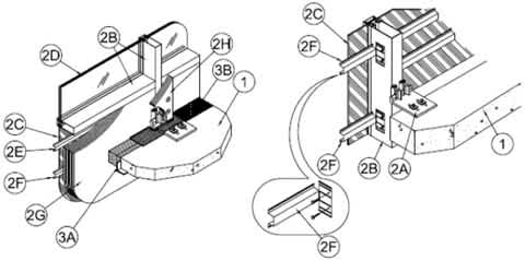
1. Floor Assembly — Min 4-1/2 in. (114 mm) thick reinforced lightweight or normal weight (100-150 pcf or 1600-2400 kg/m3) structural concrete.
2. Curtain Wall Assembly — The curtain wall assembly shall incorporate the following construction features:
A. Mullion Mounting Angles — Min 8 in. (203 mm) wide by 3/4 in. (19 mm) thick extruded aluminum Halfen mounting brackets with one nom 2 in. (51 mm) high leg for support and attachment of mullion and with one leg at least 6 in. (152 mm) longer than width of linear opening between floor assembly and mullion. Mounting bracket attached to top of floor with two min 1/2 in. (13 mm) diam steel masonry anchors in conjunction with washer plates supplied with mounting bracket.
B. Framing — The two-piece rectangular tubing mullions (vertical members) and transoms (horizontal members) shall be min 2-1/2 in. (64 mm) wide by 5 in. (127 mm) deep and shall be formed from min 0.100 in. (2.5 mm) thick aluminum. Mullions spaced max 60 in. (1.52 m) OC and secured to mullion mounting anchors (Item 2A) at each floor level in conjunction with extruded aluminum clips bolted to the sides of the mullions and designed to engage the vertical leg of the Halfen mullion mounting bracket in conjunction with an extruded aluminum hook/leveling connector. Interior face of mullions to be max 4 in. (102 mm) from edge of floor assembly. Transoms to be spaced min 36 in. (0.91 m) OC. The minimum height from the top of the floor to the bottom of the vision panel sill is 6 in. (152 mm).
C. Spandrel Panels — The spandrel panels shall consist of one of the following types:
a. Glass Panels — Nom 1/4 in. (6 mm) thick opaque heat-strengthened glass. Each panel secured in position with aluminum pressure plates in conjunction with glazing gaskets and steel screws.
b. Aluminum Panels — Nom 1/8 in. (3 mm) thick aluminum panels with 1/4 in. (6 mm) thick edges. Each panel secured in position with aluminum pressure plates in conjunction with gaskets and steel screws.
c. Stone Panels — Nom 1-3/16 in. (46 mm) thick polished granite spandrel panels with 1 in. (25 mm) thick gauged edges. Each panel secured in position with aluminum pressure plates in conjunction with gaskets and steel screws.
d. Metal Composite Panels — Min 1 in. (25 mm) thick, comprised of 0.032 in. (0.8 mm) smooth aluminum exterior skin, 0.157 in. (4 mm) thick mineral fiber cement board exterior stabilizer, 5/8 in. (16 mm) thick Micore 300 mineral fiberboard insulation core, 0.157 in. (4 mm) thick mineral fiber cement board interior stabilizer, and a 0.032 in. (0.8 mm) smooth aluminum interior skin. Each panel secured in position with aluminum pressure plates in conjunction with glazing gaskets and steel screws or with silicone structural glazing.
D. Vision Panels — Nom 1/4 in. (6 mm) thick transparent heat-strengthened glass or nom 1 in. (25 mm) thick insulated glass units with two layers of nom 1/4 in. (6 mm) thick transparent heat-strengthened glass separated by a 1/2 in. (25 mm) air space. Each panel secured in position with aluminum pressure plates in conjunction with glazing gaskets and steel screws.
E. Steel Hat Channels — Nom 2-1/2 in. (64 mm) wide by 7/8 in. (22 mm) deep No. 24 gauge (0.64 mm thick) galvanized steel hat channel installed to span from mullion-to-mullion for attachment of curtain wall insulation (Item 2G). Hat channels to be cut min 4 in. (102 mm) longer than on center spacing of mullions. Ends of hat channels cut, flattened and bent 90 deg to form min 2 in. (51 mm) long tabs for screw-attachment to mullions with No. 8 by 1 in. (25 mm) long self-drilling, self-tapping steel screws. Hat channels installed max 3 in. (76 mm) above top of vision panel, max 3 in. (76 mm) above top of concrete floor and spaced max 14 in. (356 mm) OC. When spandrel panel and horizontal transom spacing exceeds 36 in. (92 cm), the spacing of the steel hat channels may be increased to 24 in. (610 mm) OC.
F. Stiffener Channel — One nom 2-1/2 in. (64 mm) wide by 7/8 in. (22 mm) deep by 24 gauge (0.64 mm thick) (or heavier) steel hat-channel installed to span between mullions at each floor level to restrain curtain wall insulation against outward movement when forming material (Item 3A) is installed. Stiffener channel to be cut min 4 in. (102 mm) longer than on center spacing between mullions. Ends of stiffener channel cut, flattened and bent 90 deg to form min 2 in. (51 mm) long tabs for screw-attachment to the mullions (Item 2B) with No. 8 by 1 in. (25 mm) long self-drilling, self-tapping steel screws. Each stiffener channel shall be located with its stem centerline at an elevation 2 in. (25 mm) below the top plane of the floor.
G. Curtain Wall Insulation* — Nom 4 in. (102 mm) thick mineral wool batt insulation, unfaced or faced on one side with aluminum foil/scrim vapor retarder, supplied in lengths at least equal to the spandrel panel height. Insulation batts compression-fitted between vertical mullions, flush with the interior surface of framing, with a maximum of one vertical seam and with no horizontal seams. Insulation panels secured to each hat channel with min 4-1/2 in. (114 mm) long steel screws with min 1-1/2 in. (38 mm) diameter galv steel clinch shields spaced 3 in. (76 mm) from each vertical edge of batt and spaced max 24 in. (610 mm) OC between vertical edges of batt.
THERMAFIBER/OWENS CORNING — FIRESPAN 40
H. Framing Covers — Curtain Wall Insulation* — Min 8 in. (203 mm) wide strips cut from min 1 in. (25 mm) thick mineral wool batt insulation. Framing covers to be centered over mullions and secured to the steel hat channels with min 5-1/2 in. (140 mm) long steel screws. Framing covers on mullions to abut the mineral wool batt safing material (Item 3A) above and below floor. Where more than one spandrel panel occurs between vertically separated vision panels, the horizontal transom between spandrel panels shall also be covered with an 8 in. (203 mm) wide framing cover in the same manner as on the vertical mullions.
THERMAFIBER/OWENS CORNING — FIRESPAN 90
I. Weld Pin — In lieu of steel screws, No. 12 gauge (2 mm diam) galv steel weld pin with nom 1-3/16 in. (30 mm) diam galv steel cup head. Cup head weld pins provided in two lengths. One length to be equal to thickness of curtain wall insulation (Item 2G) and second length to be equal to thickness of curtain wall insulation plus thickness of framing cover (Item 2H). Cup head weld pins inserted through curtain wall insulation and mullion covers and welded to steel hat channels max 3 in. (76 mm) from each vertical edge of batt and spaced max 24 in. (610 mm) OC between vertical edges of batt.
J. Light Gauge Framing* — Spiral Anchor — (Not Shown) — As an alternate to the steel screws or weld pins (Item 2I), galv steel wire spiral anchors may be used to secure the framing covers (Item 2H) to the curtain wall insulation (Item 2G) on each side of the mullion. Nom length of spiral anchors to be equal to thickness of curtain wall insulation plus thickness of framing cover. Spiral anchors driven through mullion covers and into curtain wall insulation and spaced max 12 in. (305 mm) OC.
THERMAFIBER/OWENS CORNING
K. Aluminum Sandwich Panel — (Optional, Not Shown) — Min 1/8 in. (3.2 mm) solid aluminum panel or aluminum composite panel installed on exterior surface of curtain wall insulation (Item 2G).
3. Safing System — Max separation between edge of floor assembly and face of framing members (at the time of installation) is 4 in. The safing system is designed to accommodate vertical shear movement up to a max of 5 percent of its installed width. The safing system shall incorporate the following construction features:
A. Forming Material* — Nom 4 pcf (64 kg/m3) density mineral wool batt insulation. Batt sections cut to a min 4 in. (102 mm) width and stacked to a thickness which is min 25 percent greater than the width of linear gap between the curtain wall insulation and the edge of the concrete floor slab. The stacked forming material is compressed 20 percent in the thickness direction and inserted cut-edge-first into the linear gap such that its top surface is flush with the top surface of the floor assembly. A max of one tightly-butted seam is permitted between mullions.
THERMAFIBER/OWENS CORNING — SAF
B. Fill, Void or Cavity Material* — Min 1/8 in. (3 mm) wet thickness (min 1/16 in. (1.5 mm) dry thickness) of fill material spray-applied over top of forming material and lapping min 1/2 in. (13 mm) onto the top surface of the floor and onto the curtain wall insulation and framing covers. When SpecSeal Fast Tack Spray is used, wet and dry thickness of spray is min 5/64 in. (2 mm).