System
Technical Consulting TeamThermafiber Insolutions®
Need a modification? Want a project-specific drawing? Reach out to our Thermafiber Insolutions®
team to request an Engineering Judgment.
I-Mullion curtain wall curtain wall with glass/aluminum/stone spandrels. Reduced spandrel panel height and vision panel sill height. Firespan 40 curtain wall insulation, Safing insulation in perimeter joint, and Firespan 90 mullion covers.
Assembly Details
F Rating | 2 Hr. |
T Rating | 1/2 Hr. |
Linear Opening Width | 10 in. Max |
L Rating at Ambient | Less than 1 CFM/sq ft. |
L Rating at 400 F | Less than 1 CFM/ sq ft. |
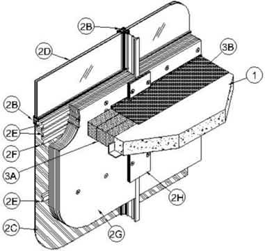
1. Floor Assembly — Min 4-1/2 in. (114 mm) thick reinforced lightweight or normal weight (100-150 pcf or 1600-2400 kg/m3) structural concrete. Perimeter of floor assembly to be provided with min 3 by 3 by 1/4 in. (76 by 76 by 6 mm) thick cast-in-place structural steel angle for weld-attachment of mullion mounting clips (Item 2A).
2. Curtain Wall Assembly — The curtain wall assembly shall incorporate the following construction features:
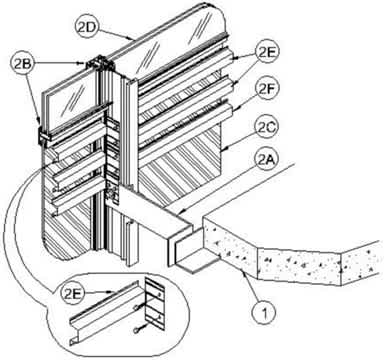
A. Mullion Mounting Angles — Min 4 in. (102 mm) long angles with one nom 4 in. (102 mm) leg for attachment to edge of floor assembly and with one leg approx 4 in. (102 mm) longer than distance to nearest face of mullion. Clips to be formed of min 1/4 in. (6 mm) thick steel. Clip welded to steel angle at edge of floor assembly (Item 1) on one side of each vertical mullion (Item 2B) at each floor level. Top edge of each clip to be recessed min 1/2 in. (13 mm) below top surface of floor. Each clip to be provided with elongated holes to accommodate designed amount of movement.
B. Framing — The "I" shaped mullions (vertical members) shall be min 2-1/2 in. (64 mm) wide by 7 in. (178 mm) deep and shall be formed from min 0.125 in. (3 mm) thick aluminum. The horizontal framing members shall be min 2 in. (51 mm) wide by 2 in. (51 mm) deep and formed from min 0.125 in. (3 mm) thick aluminum. Mullions spaced max 60 in. (152 cm) OC and secured to mullion mounting clips (Item 2A) at each floor level with two min 3/8 in. (10 mm) diameter hex head steel bolts in conjunction with steel nuts and washers. Interior face of mullions to be notched to accommodate mullion mounting clips and to be max 10 in. (254 mm) from edge of floor assembly. Horizontals to be spaced min 36 in. (91 cm) OC. The minimum height from the top of the floor to the bottom of the vision panel sill is 6 in. (152 mm).
C. Spandrel Panels — The spandrel panels shall consist of one of the following types:
a. Glass Panels — Nom 1/4 in. (6 mm) thick opaque heat-strengthened glass. Each panel secured in position and four-side captured with exterior sponge gasket compressed in place with interior wedge rubber and aluminum glazing bead.
b. Aluminum Panels — Nom 1/8 in. (3 mm) thick aluminum panels with 1/4 in. (6 mm) thick edges. Each panel secured in position and four-side captured with exterior sponge gasket compressed in place with interior wedge rubber and aluminum glazing bead.
c. Stone Panels — Nom 1-3/16 in. (46 mm) thick polished granite spandrel panels with 1 in. (25 mm) thick gauged edges. Each panel secured in position and four-side captured with exterior sponge gasket compressed in place with interior wedge rubber and aluminum glazing bead.
D. Vision Panels — Nom 1 in. (25 mm) thick (double pane) transparent heat-strengthened glass panels. Each panel secured in position and four-side captured with exterior sponge gasket compressed in place with interior wedge rubber and aluminum glazing bead.
E. Steel Hat Channels — Nom 2-1/2 in. (64 mm) wide by 7/8 in. (22 mm) deep No. 24 gauge (0.64 mm) galvanized steel hat channel installed to span from mullion-to-mullion for attachment of curtain wall insulation (Item 2G). Hat channels to be cut min 4 in. (102 mm) longer than on center spacing of mullions. Ends of hat channels cut, flattened and bent 90 deg to form min 2 in. (51 mm) long tabs for screw-attachment to mullions with No. 10 by 1 in. (25 mm) long self-drilling, self-tapping steel screws. Hat channels installed max 3 in. (76 mm) above top of vision panel, max 3 in. (76 mm) below bottom of vision panel and spaced max 24 in. (610 mm) OC. A minimum of two hat channels are required to be installed between the top of the floor and the bottom of vision panel. Hat channels screw-attached to mullions along sides of each spandrel panel with No. 10 by 1 in. (25 mm) long self-drilling, self-tapping steel screws.
F. Stiffener Channel — One nom 2-1/2 in. (64 mm) wide by 7/8 in. (22 mm) deep by 24 gauge (0.64 mm) (or heavier) steel hat-channel installed to span between mullions at each floor level to restrain curtain wall insulation against outward movement when forming material (Item 3A) is installed. Stiffener channel to be cut min 4 in. (102 mm) longer than on center spacing between mullions. Ends of stiffener channel cut, flattened and bent 90 deg to form min 2 in. (51 mm) long tabs for screw-attachment to the mullion mounting clips (Item 2A) with No. 10 by 3/4 in. (19 mm) long self-drilling, self-tapping steel screws. Each stiffener channel shall be located with its stem centerline at an elevation 2 in. (51 mm) below the top plane of the floor.
G. Curtain Wall insulation* — Nom 4 in. (102 mm) thick mineral wool batt insulation, unfaced or faced on one side with aluminum foil/scrim vapor retarder. insulation batt compression-fitted between vertical mullions, flush with the interior surface of framing, with no vertical or horizontal seams. insulation panels secured to each hat channel with min 4 1/2 in. (114 mm) long steel screws with min 1-1/2 in. (38 mm) diameter galv steel clinch shields spaced 3 in. (76 mm) from each mullion and spaced maximum 18 in. OC between mullions.
THERMAFIBER/OWENS CORNING — FIRESPAN SS insulation
H. Mullion insulation - Curtain Wall insulation* — Min 8 in. (204 mm) wide strips cut from min 1 in. thick mineral wool batt insulation. Framing covers to be centered over mullions and secured to the steel hat channels with min 5-1/2 in. (140 mm) long steel screws. Framing covers on mullions to abut the mineral wool batt safing material (Item 3A) above and below floor.
THERMAFIBER/OWENS CORNING — FIRESPAN insulation
3. Safing System — Max separation between edge of floor assembly and face of framing members (at time of installation) is 10 in. The safing system is designed to accommodate vertical shear movement up to a max of 5 percent of its installed width. The safing system shall incorporate the following construction features:
A. Forming Material* — Nom 4 pcf (64 kg/m3) density mineral wool batt insulation. Batt sections cut to a 4 in. (102 mm) width and stacked to a thickness which is min 20 percent greater than the width of the linear gap between the curtain wall insulation and the edge of the concrete floor slab. The forming material is compressed and inserted cut-edge-first into linear gap such that its top surface is flush with the top surface of the floor assembly. A max of one tightly-butted seam is permitted between mullions. Additional piece of forming material to be friction-fit into gap between batt sections above mullion mounting clip at each mullion location.
THERMAFIBER/OWENS CORNING — SAF
B. Fill, Void or Cavity Material* — Min 1/8 in. (3 mm) wet thickness (min 1/16 in. (1.5 mm) dry thickness) of fill material spray-applied over top of forming material and lapping min 1/2 in. (13 mm) onto the top surface of the floor and onto the curtain wall insulation and mullion covers. When SpecSeal Fast Tack Spray is used, wet and dry thickness of spray is min 5/64 in. (2 mm).
SPECIFIED TECHNOLOGIES INC — SpecSeal AS200 Elastomeric Spray, SpecSeal Safing Spray or SpecSeal Fast Tack Spray
* Indicates such products shall bear the UL or cUL Certification Mark for jurisdictions employing the UL or cUL Certification (such as Canada), respectively.