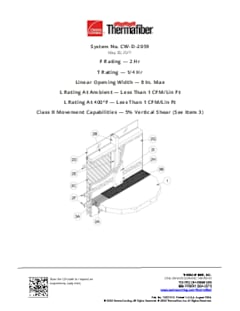
SystemCW-D-2059
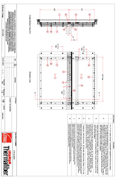
Assembly Details
Need a modification? Want a project-specific drawing? Reach out to our Thermafiber Insolutions®
team to request an Engineering Judgment.
Aluminum framed curtain wall with glass, aluminum, stone/granite spandrel. Min. 60" Spandrel. Spandrel perimeter angle, 2 backer reinforcment members outboard of Thermafiber 2" Firespan 90. Thermafiber® Safing Insulation. Passive Fire Protection Partners Sealant.
F Rating | 2 Hr. |
T Rating | 1/4 Hr. |
Linear Opening Width | 8 in Max. |
L Rating at Ambient | Less than 1 CFM/Lin Ft. |
L Rating at 400 F | Less than 1 CFM/Lin Ft. |
1. Min 4-1/2 in. (114 mm) thick reinforced lightweight or normal weight (100-150 pcf or 1600-2400 kg/m3 ) structural concrete. Perimeter of floor assembly to be provided with min 3 by 3 by 1/4 in. (76 by 76 by 6 mm) thick cast-in-place structural steel angle for weld-attachment of mullion mounting clips (Item 2A).
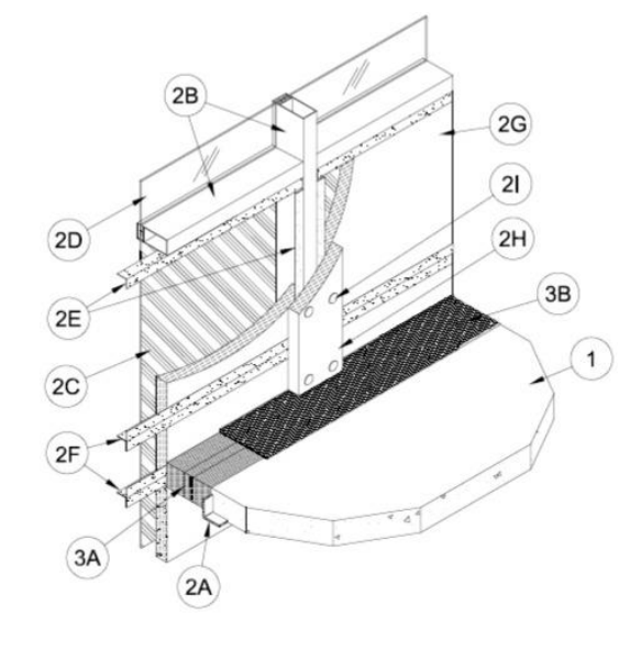
2. The curtain wall assembly shall incorporate the following construction features:
A. Mullion Mounting Clips — Min 4 in. (102 mm) long angles with one nom 4 in. (102 mm) leg for attachment to edge of floor assembly and with one leg approx 4 in. (102 mm) longer than distance to nearest face of mullion. Clips to be formed of min 1/4 in. (6 mm) thick steel. Clips welded to steel angle at edge of floor assembly (Item 1) on each side of vertical mullion (Item 2B) at each floor level. Each clip to be provided with elongated holes to accommodate the designed amount of vertical movement. Top edge of each clip to be recessed min 1/2 in. (13 mm) below top surface of floor.
B. Framing — The rectangular tubing mullions (vertical members) and transoms (horizontal members) shall be min 2-1/2 in. (64 mm) wide by 5 in. (127 mm) deep and shall be formed from min 0.085 in. (2.2 mm) thick aluminum. Mullions spaced max 60 in. (1.52 m) OC and secured to mullion mounting clips (Item 2A) at each floor level with two 3/8 in. (10 mm) diam by 4 in. (102 mm) long hex head steel bolts in conjunction with steel nuts and washers . Interior face of mullions to be max 8 in. (203 mm) from edge of floor assembly. Transoms to be spaced min 60 in. (1.52 m) OC. Transom forming sill of vision panel (Item 2D) to be located such that its bottom surface is at a min height of 24 in. (610 mm) above the top surface of the floor.
C. Spandrel Panels — The spandrel panels shall consist of one of the following types: a. Glass Panels — Nom 1/4 in. (6 mm) thick opaque heat-strengthened glass. Each panel secured in position with aluminum pressure plates in conjunction with glazing gaskets and steel screws. b. Aluminum Panels — Nom 1/8 in. (3 mm) thick aluminum panels with 1/4 in. (6 mm) thick edges. Each panel secured in position with aluminum pressure plates in conjunction with gaskets and steel screws. c. Stone Panels — Nom 1-3/16 in. (30 mm) thick polished granite spandrel panels with 1 in. (25 mm) thick gauged edges. Each panel secured in position with aluminum pressure plates in conjunction with gaskets and steel screws.
D. Vision Panels — Nom 1/4 in. (6 mm) thick transparent heat-strengthened glass or nom 1 in. (25 mm) thick insulated glass units with two layers of nom 1/4 in. (6 mm) thick transparent heat-strengthened glass separated by a 1/2 in. (25 mm) air space. Each panel secured in position with aluminum pressure plates in conjunction with glazing gaskets and steel screws.
E. Spandrel Panel Perimeter Angles — Nom 1-1/2 by 1-1/2 in. (38 by 38 mm) No. 20 gauge (min 0.034 in. or 0.86 mm thick) galv steel angles installed around entire perimeter of each spandrel panel, flush with inside face of mullions and transoms. Angles notched at mullion mounting clips (Item 2A). Angles screw-attached to mullions and transom along sides and top of each spandrel panel with No. 8 by 1 in. (25 mm) long self-drilling, self-tapping steel screws spaced max 12 in. (305 mm) OC. Angle along bottom of each spandrel panel to be screw-attached to leg of angle on mullion at each end without any direct attachment to transom.
F. Stiffener Tee — Two nom 1-1/2 by 1-1/2 in. (38 by 38 mm) No. 20 gauge (min 0.034 in. or 0.86 mm thick) galv steel angles secured together, back-to-back, to form stiffener tee for installation in each horizontal seam of the curtain wall insulation (Item 2G). The angle legs forming the stem of the tee shall be secured together using No. 8 by 1/2 in. (13 mm) long self-drilling, self-tapping steel screws spaced max 8 in. (203 mm) OC. The tee shall be installed with a clearance of 1/8 to 1/4 in. (3 to 6 mm) at each end and shall be screw-attached to the spandrel panel perimeter angles (Item 2E) with No. 10 by 3/4 in. (19 mm) long self-drilling, self-tapping steel screws, with steel washers, through two predrilled 1/4 in. (6 mm) diam holes at each end. One stiffener tee shall be located with its stem at an elevation 2 in. (51 mm) below the top plane of the floor at each floor level. Additional stiffener tee located with its stem a min of 6 in. (152 mm) above the top surface of the floor.
G. Curtain Wall Insulation* — Min 2 in. (51 mm) thick mineral wool batt insulation faced on one side with aluminum foil/scrim vapor retarder, supplied in min 36 in. (0.91 m) wide batts. Insulation panels to be installed with no vertical seams. Insulation panels tightly-fitted between vertical mullions and between the stems of the stiffener tees (Item 2F) and the transoms. Insulation panels secured to spandrel panel perimeter angles and to each stiffener tee with cup head weld pins (Item 2I) spaced max 12 in. (305 mm) OC. The horizontal seams between insulation panels shall be located 2 in. (51 mm) below the top plane of the floor at each floor level and a min of 6 in. (152 mm) above the top surface of the floor. THERMAFIBER INC — FIRESPAN 90
H. Framing Covers — Curtain Wall Insulation* — Min 8 in. (203 mm) wide strips cut from the same min 2 in. (51 mm) thick mineral wool batt insulation used for the curtain wall insulation (Item 2G). Framing covers to be centered over mullions and secured to the spandrel panel perimeter angles with cup head weld pins (Item 2I) spaced max 12 in. (305 mm) OC. Where more than one spandrel panel occurs between vertically separated vision panels, the horizontal transom between spandrel panels shall also be covered with an 8 in. (203 mm) wide framing cover in the same manner as on the vertical mullions. Framing covers on mullions to abut the mineral wool batt safing material (Item 3A) above and below floor. THERMAFIBER INC — FIRESPAN 90
I. Weld Pin — No. 12 gauge galv steel weld pin with nom 1-3/16 in. (30 mm) diam galv steel cup head. Length of Cup head weld pins to be equal to thickness of curtain wall insulation (Item 2G) and framing cover (Item 2H). Cup head weld pin inserted through curtain wall insulation or framing cover and welded to spandrel panel perimeter angles and to stiffener tees max 12 in. (305 mm) OC.
J. Light Gauge Framing* - Spiral Anchor — (Not Shown) - As an alternate to the weld pins (Item 2I), galv steel wire spiral anchors may be used to secure the framing covers (Item 2H) to the curtain wall insulation (Item 2G) on each side of the mullion. Nom length of spiral anchors to be equal to thickness of curtain wall insulation plus thickness of framing cover. Spiral anchors driven through mullion covers and into curtain wall insulation and spaced max 12 in. OC. THERMAFIBER INC
3. Max separation between edge of floor assembly and face of framing members (at time of installation) is 8 in. (203 mm). The safing system is designed to accommodate vertical shear movement up to a max of 5 percent of its installed width. The safing system shall incorporate the following construction features:
A. Forming Material* — Nom 4 pcf (64 kg/m3 ) density mineral wool batt insulation. Batt sections cut to a min 4 in. (102 mm) width and stacked to a thickness which is min 20 percent greater than the width of linear gap between the curtain wall insulation and the edge of the concrete floor slab. The forming material is compressed and inserted cut-edge-first into linear gap such that its top surface is flush with the top surface of the floor assembly. A max of one tightly-butted seam is permitted between mullions. Additional pieces of forming material to be friction-fit into spaces between mullion mounting clips at each mullion location. THERMAFIBER INC — SAF
B. Fill, Void or Cavity Material* — Min 1/8 in. (3 mm) wet thickness (min 1/16 in. or 1.5 mm dry thickness) of fill material spray-applied over top of forming material and lapping min 1/2 in. (13 mm) onto the top surface of the floor and onto the curtain wall insulation and framing covers. PASSIVE FIRE PROTECTION PARTNERS — 5100SP
* Indicates such products shall bear the UL or cUL Certification Mark for jurisdictions employing the UL or cUL Certification (such as Canada), respectively.