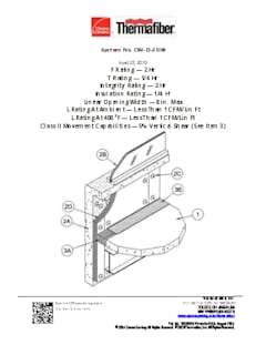
System
Technical Consulting TeamThermafiber Insolutions®
Need a modification? Want a project-specific drawing? Reach out to our Thermafiber Insolutions®
team to request an Engineering Judgment.
Precast concrete or tilt-up panels with min 2" Firespan 90 curtain wall insulation. Reduced spandrel panel height and vision panel sill height. Please use screws/washers as the fasteners. Safing Insulation in perimeter joint.
Assembly Details
F Rating | 2 Hr. |
T Rating | 1/4 Hr. |
Linear Opening Width | 8 in. Max |
L Rating at Ambient | Less than 1 CFM/ Lin ft. |
L Rating at 400 F | Less than 1 CFM/ Lin ft. |
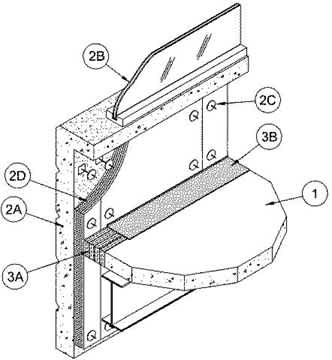
1. Floor Assembly — Min 4-1/2 in. (114 mm) thick steel-reinforced lightweight or normal weight (100-150 pcf or 1600-2400 kg/m3) structural concrete. Floor assembly to be supported at perimeter edges by spandrel beams having a Restrained or Unrestrained Beam Rating of 2 hr. Edge of concrete floor to be max 8 in. from interior surface of spandrel panel (Item 2A
2. Curtain Wall Assembly — The curtain wall assembly shall incorporate the following construction features:
A. Spandrel Panels — Min 36 in. (92 cm) high by min 4 in. (102 mm) thick steel-reinforced lightweight or normal weight (100-150 pcf or 1600-2400 kg/m3) structural concrete spandrel panels. Wall may also consist of min 4 in. (102 mm) thick steel-reinforced lightweight or normal weight concrete tilt-up panels with a min 36 in. (92 cm) vertical separation between window openings. Panels provided with steel dead load anchors welded to steel reinforcing bars embedded in the concrete for attachment to the steel columns and spandrel beams. Panels also provided with steel lateral anchors or braces. The dead load anchors, which are located in the linear gap between the concrete floor slab and the spandrel panel or tilt-up panel, are to be spaced max 72 in. (183 cm) OC. The top of the dead load anchor is to be recessed min 1/2 in. (13 mm) from top surface of floor.
B. Framed Window — Metal framed window with nom 1 in. (25 mm) thick (double pane) transparent heat-strengthened glass panels. Sill of window to be min 6 in. (152 mm) above top of floor.
C. Impaling Pins — No. 12 gauge (2 mm) steel pins, min 1/2 in. (13 mm) longer than thickness of insulation boards (Item 2D), swaged to nom 2 by 2 in. (51 by 51 mm) galv steel base plate. Steel base plates secured to concrete spandrel panel with steel concrete screws or powder-driven steel fasteners. Impaling pins to be spaced 3 in. (76 mm) from edges of insulation boards (Item 2D) on each side of seams and spaced max 24 in. (610 mm) OC both vertically and horizontally. A min of two horizontal arrays of impaling pins are required to be located on spandrel panel above top surface of floor.
C1. Clutch Clips — (Optional, Not Shown) - Nom 2 by 2 in. (51 by 51 mm) wide by 1-1/4 in. (32 mm) high V-shaped steel clutch clips used in conjunction with impaling pins (Item 2C) to offset curtain wall insulation (Item 2D) from spandrel panel (Item 2A). Clutch clips to be used on all impaling pins. When clutch clips are used, a row of impaling pins shall be located max 3 in. (76 mm) from top and bottom surfaces of floor assembly and spaced max 18 in. (457 mm) OC.
D. Curtain Wall Insulation* — Min 2 in. (51 mm) thick mineral wool board insulation, unfaced or faced on one side with aluminum foil/scrim vapor retarder, supplied in min 24 by 48 in. (61 by 122 cm) boards. Insulation boards installed vertically with tightly-butted seams to cover interior surface of concrete spandrel panel. Horizontal seams of insulation boards (if necessary) to be located min 6 in. (152 mm) above and min 6 in. (152 mm) below planes of floor. Insulation boards secured to spandrel panel with impaling pins in conjunction with min 1-1/2 in. (38 mm) diameter galv steel clinch shields. Butted seams to be covered with aluminum foil tape.
THERMAFIBER/OWENS CORNING — FIRESPAN 90
3. Safing System — Max separation between edge of floor assembly and curtain wall insulation is 6 in. (152 mm). The safing system is designed to accommodate vertical shear movement between dead load anchors up to a max of 5 percent of its installed width between the edge of the floor assembly and the curtain wall insulation. The safing system shall incorporate the following construction features:
A. Forming Material* — Mineral wool batt safing material to be cut into min 4 in. (102 mm) wide pieces and stacked to a thickness which is at least 25 percent greater than the width of the linear gap between the curtain wall insulation (Item 2D) and the edge of the concrete floor slab. The stacked safing material is compressed and inserted cut-edge-first into the linear gap such that its top surface is flush with the top surface of the floor assembly. A max of one tightly butted seam is permitted between spandrel panel attachment plates or tubes. An additional min 1/2 in. (13 mm) thick piece of mineral wool batt safing material is to be installed to cover top surface of each dead load anchor.
THERMAFIBER/OWENS CORNING — SAF
B. Fill, Void or Cavity Material* — Min 1/8 in. (3 mm) wet thickness (1/16 in. (1.5 mm) dry) of fill material spray-applied over top of forming material and lapping min 1/2 in. (13 mm) onto the top surface of the concrete floor and onto the curtain wall insulation. When SpecSeal Fast Tack Spray is used, wet and dry thickness of spray is min 5/64 in. (2 mm).
SPECIFIED TECHNOLOGIES INC — SpecSeal AS200 Elastomeric Spray, SpecSeal Safing Spray or SpecSeal Fast Tack Spray