System
Technical Consulting TeamThermafiber Insolutions®
Need a modification? Want a project-specific drawing? Reach out to our Thermafiber Insolutions®
team to request an Engineering Judgment.
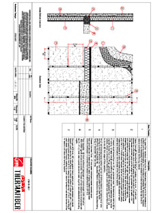
Thin concrete panels on steel studs with glass fiber in stud cavities. Safing Insulation in perimeter joint.
Assembly Details
F Rating | 2 Hr. |
T Rating | 1/4 Hr. |
Linear Opening Width | 2-1/2 in. Max. |
L Rating at Ambient | Less than 1 CFM/Lin ft. |
L Rating at 400 F | Less than 1 CFM/ Lin ft. |
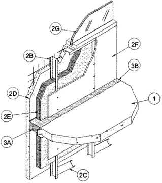
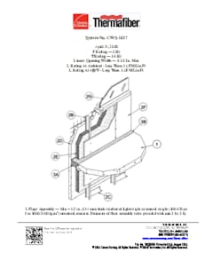
1. Floor Assembly — Min 4-1/2 in. (114 mm) thick reinforced lightweight or normal weight (100-150 pcf or 1600-2400 kg/m3) structural concrete. Perimeter of floor assembly to be provided with min 3 by 3 by 1/4 in. (76 by 76 by 6 mm) thick cast-in-place structural steel angle for weld-attachment of mounting angles (Item 2A).
2. Curtain Wall Assembly — The curtain wall assembly shall incorporate the following construction features:
A. Mounting Angles — (Not Shown) - Min 3 in. (76 mm) long angles with one min 2 in. (51 mm) leg for attachment to edge of floor assembly and with one leg approx 2-1/2 to 3 in. (64 by 76 mm) longer than distance to interior face of steel studs. Angles to be formed of min 1/8 in. (3 mm) thick steel. Angles welded to cast-in-place structural steel angle at edge of floor assembly (Item 1) on one side of each steel stud (Item 2B) at each floor level. Top edge of each mounting angle to be recessed 1 to 1-1/2 in. (38 mm) below top surface of floor.
B. Steel Studs — C-shaped studs formed from min 0.034 in. (0.9 mm) thick galv steel. The steel studs shall be 3-1/2 in. to 6 in. (89 to 152 mm) wide by 1-1/4 in. (32 mm) deep with 5/16 in. (8 mm) wide stiffening flanges and shall be assembled using runner channels formed from min 0.034 in. (0.9 mm) thick galv steel. Studs spaced max 24 in. (610 mm) OC and welded, bolted or screwed to mounting angles (Item 2A) at each floor level. Interior face of studs to be max 2-1/2 in. (64 mm) from edge of floor assembly.
C. Steel Struts — Short lengths of steel stud (Item 2B) used to brace each steel stud against lateral movement. One end of strut bolted, screwed or welded to steel stud beneath plane of floor assembly. Opposite end of strut anchored to underside of floor.
D. Precast Concrete Panel — Nom 2 in. (51 mm) thick steel-reinforced precast concrete panel. Each panel secured to steel studs by means of epoxy coated stainless steel anchors embedded in concrete and welded to steel studs on 24 in. (610 mm) centers.
E. Batts and Blankets* — Any glass fiber insulation bearing the UL Classification Marking as to fire resistance or surface burning characteristics, of a thickness to completely fill stud cavity. Insulation batts friction fit to completely fill all stud cavities of curtain wall above the top of the fill material (Item B) and below the forming material (Item 3A).
See Batts and Blankets (BZJZ) category for names of manufacturers.
F. Gypsum Board* — One layer of nom 5/8 in. (16 mm) thick, 48 in. (1.22 m) wide gypsum board applied with joints centered over studs. Gypsum board secured to steel studs on interior surface of curtain wall with min 1 in. (25 mm) long bugle head steel screws spaced max 8 in. (204 mm) OC along the edges and max 12 in. (305 mm) OC in the field of each sheet. Gypsum board installed to cover interior surface of wall above the top of the fill material (Item 3C) and below the forming material (Item 3B).
See Gypsum Board (CKNX) category for names of Classified Companies and product types.
G. Framed Window — Metal-framed window with nom 1/4 in. (6 mm) thick heat-strengthened glass. Sill of window to be min 6 in. (152 mm) above top of floor slab. Top of window to be min 30 in. (76 cm) below bottom of floor slab.
3. Safing System — The safing system shall incorporate the following construction features:
A. Forming Material* — Nom 4 pcf (64 kg/m3) density mineral wool batt insulation. Batt sections to be cut to a min width of 4 in. (102 mm) and stacked to a thickness which is 25 percent greater than the width of the linear gap between the precast concrete panel and the edge of the concrete floor to attain a min 20 percent compression in the thickness direction. The forming material is compressed and inserted cut-edge-first into linear gap between edge of floor slab and sheathing material such that its top surface is flush with the top surface of the floor assembly. Length of batt to be equal to on-center spacing of steel studs such that it is friction-fitted between studs and mounting angles without seams. Additional pieces of mineral wool batt to be stuffed inside the channel of each steel stud throughout the thickness of the forming material.
THERMAFIBER/OWENS CORNING — SAF
B. Fill, Void or Cavity Material* — Min 1/8 in. (3 mm) wet thickness (min 1/16 in. (1.6 mm) dry) of fill material spray-applied over top of forming material and lapping min 1/2 in. (13 mm) onto the top surface of the floor and onto the gypsum sheathing and steel studs.
SPECIFIED TECHNOLOGIES INC — SpecSeal AS200 Elastomeric Spray, SpecSeal Safing Spray or SpecSeal Fast Tack Spray