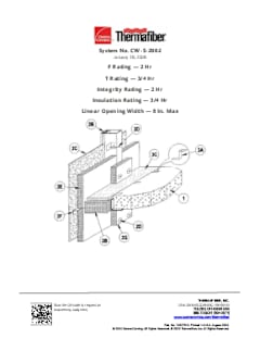
SystemCW-S-2002
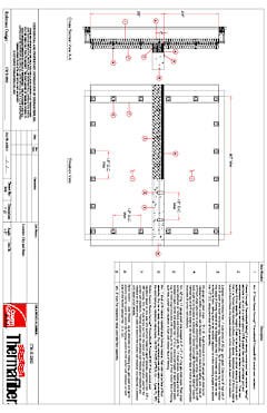
Assembly Details
Need a modification? Want a project-specific drawing? Reach out to our Thermafiber Insolutions®
team to request an Engineering Judgment.
Aluminum framed curtain wall with aluminum spandrel. 2- HR. F and Integrity Rating. Min. 72" Spandrel. Impaling pins. Thermafiber® 2" Firespan® 90 and Safing insulation. USG Sealant.
F Rating | 2 Hr. |
T Rating | 3/4 Hr. |
Integrity Rating | 2 Hr. |
insulation Rating | 3/4 Hr. |
Linear Opening Width | 8 in Max. |
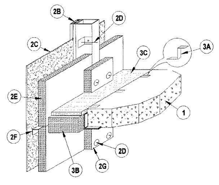
1. Min 5 in. thick reinforced lightweight or normal weight (100-150 pcf) structural concrete. Perimeter of floor assembly to be provided with min 4 by 4 by 1/4 in. thick cast-in-place structural steel angle for weld-attachment of mullion mounting angles (Item 2A).
2. The curtain wall assembly shall incorporate the following construction features:
A. Mullion Mounting Angles — Min 5 in. long angles with one nom 4 in. leg for attachment to edge of floor assembly and with one leg approx 2 in. longer than distance to nearest face of mullion. Angles to be formed of min 1/4 in. thick steel. Angles welded to steel angle at edge of floor assembly (Item 1) on each side of vertical mullion (Item 2B) at each floor level. Top edge of each angle to be recessed 1 to 2 in. below top surface of floor.
B. Framing — The rectangular tubing mullions (vertical members) and transoms (horizontal members) shall be minimum 2-1/2 in. wide by 4-1/2 in. deep and shall be formed from min 0.100 in. thick aluminum. Mullions spaced max 60 in. OC and secured to steel mounting angles (Item 2A) at each floor level with two 3/8-16 by 4 in. long hex head steel bolts in conjuction with anchor sleeves. Interior face of mullions to be max 8 in. from edge of floor assembly. Transoms to be spaced min 72 in. OC. Transom above perimeter joint system to be located such that its bottom surface is at a height of 33 in. above the top surface of the floor (Item 1).
C. Spandrel Panels — Min 1/8 in. thick aluminum panels with 1/4 in. thick edges. Each panel secured in position with aluminum retainers in conjuction with glazing gaskets and steel screws.
D. Impaling Pins — Min 4-1/2 in. long 12 gauge steel pins swaged to nom 2 by 2 by 2 in. long galv steel angle. Steel angle screw-attached to mullions and transoms with No. 12 steel screws. Impaling pins to be located in each corner and spaced max 12 in. OC around perimeter of each spandrel panel. Leg of steel angle provided with impaling pin to be recessed 2 in. from interior face of framing such that curtain wall insulation (Item 2E) is flush with interior face of framing.
E. Curtain Wall insulation* — Min 2 in. thick mineral wool batt insulation, unfaced or faced on one side with aluminum foil/scrim vapor retarder, supplied in nom 36 in. wide batts. insulation batts installed over entire interior surface of curtain wall. insulation batts to be installed with no vertical seams and with horizontal seams spaced min 36 in. OC. insulation panels tightly-fitted between vertical mullions and impaled on pins (Item 2D), flush with interior surface of framing, and secured in position with min 1-1/2 in. diam steel clinch shields. The horizontal seam between insulation panels shall be located 3 in. below the top plane of the floor at each floor level. THERMAFIBER INC — FIRESPAN 90
F. Stiff Back Angle — Nom 1-1/2 by 1-1/2 in. angle formed of min 20 gauge galv steel to be installed to stiffen curtain wall insulation between vertical mullions at safing joint. Ends of stiff back angle secured to angle attachment clips (Item 2G) with steel screws. Horizontal leg of stiff back angle to be located at midheight of forming material (Item 3B). Vertical leg of stiff back angle to be recessed from interior face of mullion to accommodate thickness of curtain wall insulation (Item 2E) .
G. Angle Attachment Clip — Nom 1-1/2 by 1-1/2 by 1-1/2 in. long angle formed of min 20 gauge galv steel. Angle attachment clips welded or screw-attached to mullion mounting angles (Item 2A) for attachment of stiff back angles (Item 2F) .
H. Framing Covers — Curtain Wall insulation* — Min 8 in. wide strips cut from the same nom 2 in. thick mineral wool batt insulation used for the curtain wall insulation (Item 2E). Framing covers to be centered over mullions and transoms and impaled on the same pins used to secure the curtain wall insulation and secured in position with steel clinch shields. THERMAFIBER INC — FIRESPAN 90
I. Light Gauge Framing* - Spiral Anchor — (Not Shown) - As an alternate to the impaling pins (Item 2D), galv steel wire spiral anchors may be used to secure the framing covers (Item 2H) to the curtain wall insulation (Item 2E) on each side of the mullion. Nom length of spiral anchors to be equal to thickness of curtain wall insulation plus thickness of framing cover. Spiral anchors driven through mullion covers and into curtain wall insulation and spaced max 12 in. OC. THERMAFIBER INC
3. The perimeter fire containment system shall incorporate the following construction features:
A. Support Clips — Z-shaped clips formed from 1 in. wide strips of 20 ga galv steel. Clips to be 3 in. high with 2 in. and 3 in. upper and lower horizontal legs, respectively. The 3 in. horizontal leg is to be impaled into edge of forming material (Item 3B) at its middepth and the 2 in. horizontal leg is to rest on top surface of floor. Safing clips to be located adjacent to mullion mounting angles (Item 2A) and spaced max 12 in. OC along perimeter of floor assembly.
B. Forming Material* — Nom 4 in. thick, nom 4 pcf density mineral wool batt insulation. Batt sections to be cut to a width approx 25 percent greater than width of perimeter joint and compression-fitted into perimeter joint such that its top surface is recessed 1 in. from top surface of floor assembly. Length of batt to be equal to on center spacing of mullions such that it is friction-fitted between mullions without seams. Additional pieces of forming material to be friction-fitted into spaces between mullion mounting angles at each mullion location. THERMAFIBER INC — SAF
C. Fill, Void or Cavity Material* — Min 1 in. thickness of fill material installed atop forming material, flush with top surface of floor assembly. Dry mix or ready-mix material. Dry mix material mixed with water in accordance with the accompanying installation instructions. UNITED STATES GYPSUM CO — FC, RFC
* Indicates such products shall bear the UL or cUL Certification Mark for jurisdictions employing the UL or cUL Certification (such as Canada), respectively.